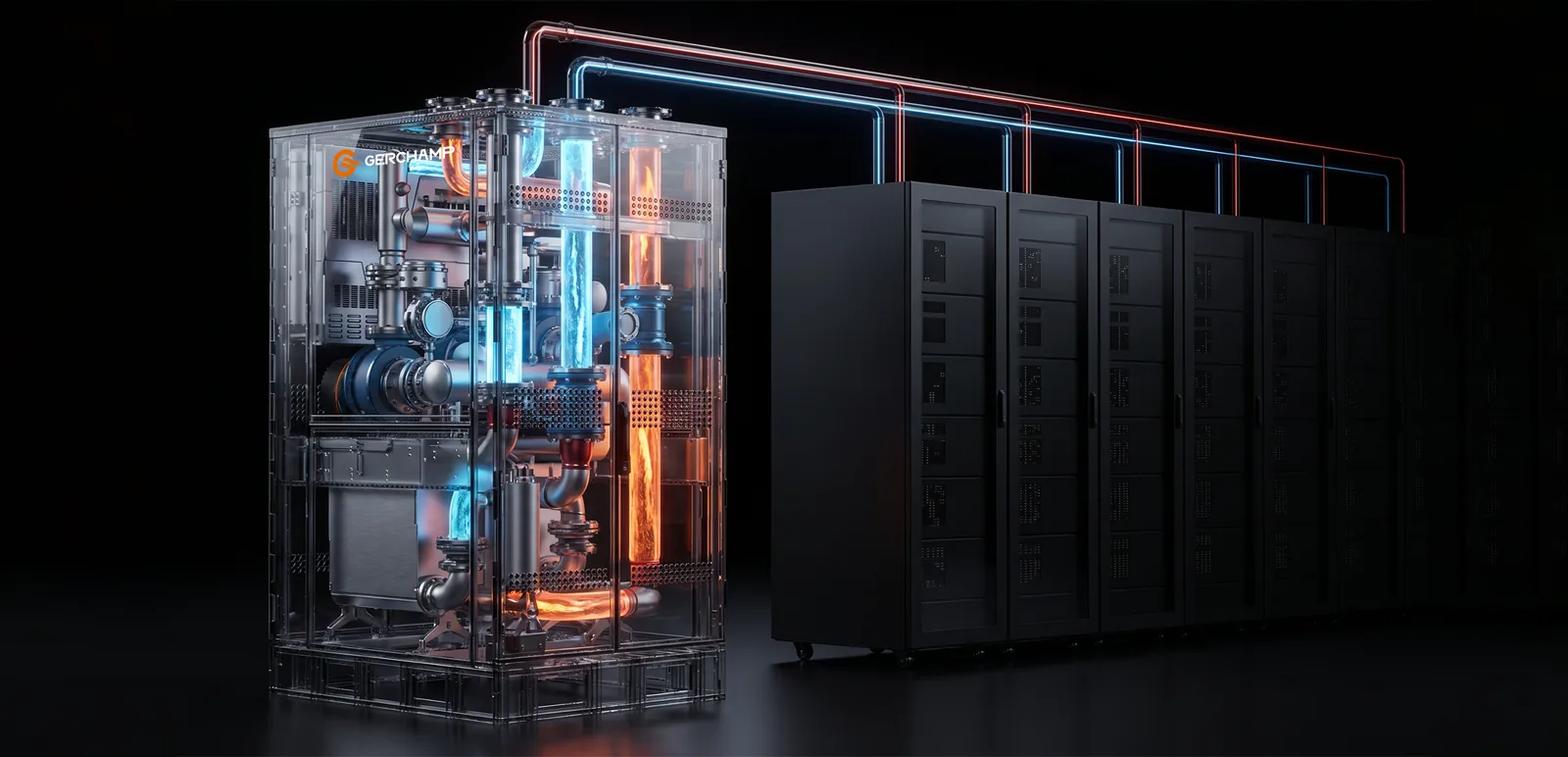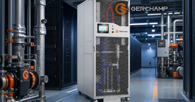
A coolant distribution unit sits between the rack loop and the building’s heat rejection path, and holds coolant temperature and flow at setpoint on the IT side.
The coolant distribution unit components are a pump set, a heat exchanger or a coil, filtration, a reservoir, valves, sensors, and a controller. That list describes a common configuration. Individual products differ in how many of these they integrate, and in which ones are optional.
The differences matter at specification time. Two units with the same function list can differ in rack space, service access, and what they expect from the building.
The CDU in the Cooling Chain
A CDU in the cooling chain occupies the joint between the loop that reaches the chips and the loop or air path that carries heat to the plant or to the room. It holds conditions on the IT side and hands the collected heat to whatever rejects it.
That position explains the contents. A liquid-to-liquid unit brings two liquid circuits into one enclosure. A liquid-to-air unit brings in one circuit and rejects heat to room air.
The contents also follow the architecture. The heat exchange group changes shape between a plate exchanger and a coil. The other groups change less, though their instrumentation still varies by product.
Position in the loop
The secondary loop runs from the CDU supply port to the rack manifolds, through the cold plates, and back to the return port. On a liquid-to-liquid unit the other side is facility water. On a liquid-to-air unit it is room air drawn across the coil.
Two Sides, One Enclosure
A liquid-to-liquid unit monitors two liquid streams. A liquid-to-air unit monitors one liquid stream, and its capacity also depends on the air temperature and flow across the coil.
Scope limits
The unit does not create cooling. Cooling usually comes from a chiller, a dry cooler, a cooling tower, or the room air handling. Cold plates, hoses, and rear-door exchangers sit outside the enclosure in most designs. Some products offer internal manifolds as an option, so the split belongs in the model drawing. Which part of the chain each device covers is set out in CDU vs chiller.
CDU Parts and What Each One Does
CDU parts group by function. Three groups cover the work: circulation with storage, heat exchange, and sensing with control. Fluid management, which includes filtration, filling, venting, and draining, cuts across the first group and deserves its own reading.
A parts list sorted this way survives a hardware change. The function stays, and the part that serves it can differ between products.
Circulation and storage
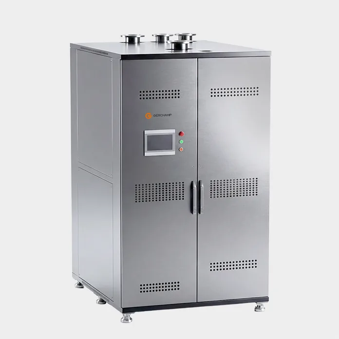
The pump set moves coolant and provides the head the loop needs. A single pump appears in light units. Two pumps in a lead-lag or 1+1 arrangement appear in units built for redundant operation, and the 2,700 kW class adds a third pump in a 2+1 layout. Gerchamp’s CDU32700 L2L 2700kW is specified that way.
The reservoir and the expansion tank do different jobs. A reservoir provides coolant storage and may support filling, make-up and pump suction. An expansion tank absorbs the volume change as coolant temperature varies and helps hold system pressure. One vessel can serve both roles where the design provides for it, and a design may also separate them.
Filtration and fluid management
Filtration keeps particles out of narrow passages. Which component it protects depends on where the filter sits: a primary-side filter protects the exchanger, a secondary-side filter protects the cold plates. The rating follows the circuit, the coolant cleanliness and the allowable pressure drop.
Filling, venting, and draining are separate functions with their own hardware. Air left in a loop collects at high points and reduces flow. A drain point decides whether a branch can be emptied for service. Automatic air vents and drain valves appear on many units, and their location belongs on the drawing.
Heat exchange
A liquid-to-liquid unit usually carries a plate heat exchanger, where facility water takes the heat across a plate wall. A liquid-to-air unit usually carries a coil and a fan set, where room air takes the heat.
This group is where the two architectures diverge. It also sets part of the pressure drop that the pump has to overcome on the secondary side.
Sensing and control
Sensors serve two purposes. Some close a control loop, and others raise an alarm. Depending on the control architecture, supply temperature may drive a valve or fan speed, and differential pressure at a chosen reference point may drive pump speed. Level, leak, and filter differential pressure sensors mostly feed alarms.
The controller acts on the unit’s own pumps, valves, and fans. Coordination with the plant belongs to the control interface and the project design, and the protocol list sits on the datasheet. Pumps may hold flow or differential pressure, while a valve or fan speed holds supply temperature.
| Part | Duty | L2A vs L2L | Varies by model |
|---|---|---|---|
| Pump set | Provides flow and head | Same group in both | Single, 1+1, or 2+1 |
| Reservoir | Make-up volume, stable suction | Same group in both | May be combined with an expansion tank |
| Expansion tank | Absorbs volume change | Same group in both | May be integrated or separate |
| Filter | Keeps particles out of narrow passages | Same group in both | Circuit, cleanliness and pressure drop |
| Control valve | Regulates flow, mixing or bypass | Location follows the architecture | Type, actuator and control strategy |
| Isolation valve | Closes a branch for service | Same group in both | Manual or actuated |
| Heat exchanger | Transfers heat to facility water | L2L only | Plate count and material |
| Coil and fans | Transfers heat to room air | L2A only | Coil face area and fan type |
| Air vent and drain | Removes air, empties a branch | Same group in both | Automatic or manual |
| Sensors | Temperature, pressure, flow, level, leak | Air side reads room temperature on L2A | Point list varies |
| Controller | Acts on the unit’s own parts | Same group in both | Protocol list varies |
CDU Form Factors and the Space Each One Takes
CDU form factors describe where the enclosure stands. They do not set the capacity class, and the two are often confused in a tender.
Four placement costs follow from the choice: rack units, floor area, hose or pipe length, and service clearance. Each one is measurable before any datasheet comparison.
Rack-mounted units
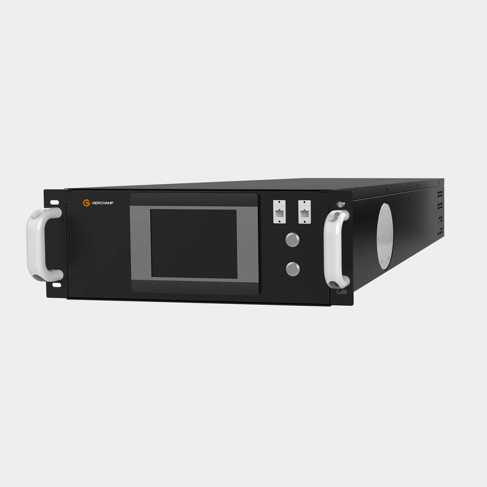
A rack-mounted unit occupies U space inside the cabinet it serves. It generally avoids a separate equipment footprint and may shorten the liquid path to the manifold, depending on the cabinet and manifold arrangement. It also takes U space that would otherwise hold servers, and it puts service access inside the row.
In-row units
An in-row unit stands in line with the cabinets, at the end of a row or between two rows. It keeps the rack space intact and gives the technician room to work. Floor area and a route for hoses or pipework are the costs.
Capacity does not follow from the position. Gerchamp’s CDU32700 L2L 2700kW is an in-row unit at 1,200 × 1,200 mm rated 2,700 kW, and a 4U unit in the same product line is rated far lower.
Sidecar units
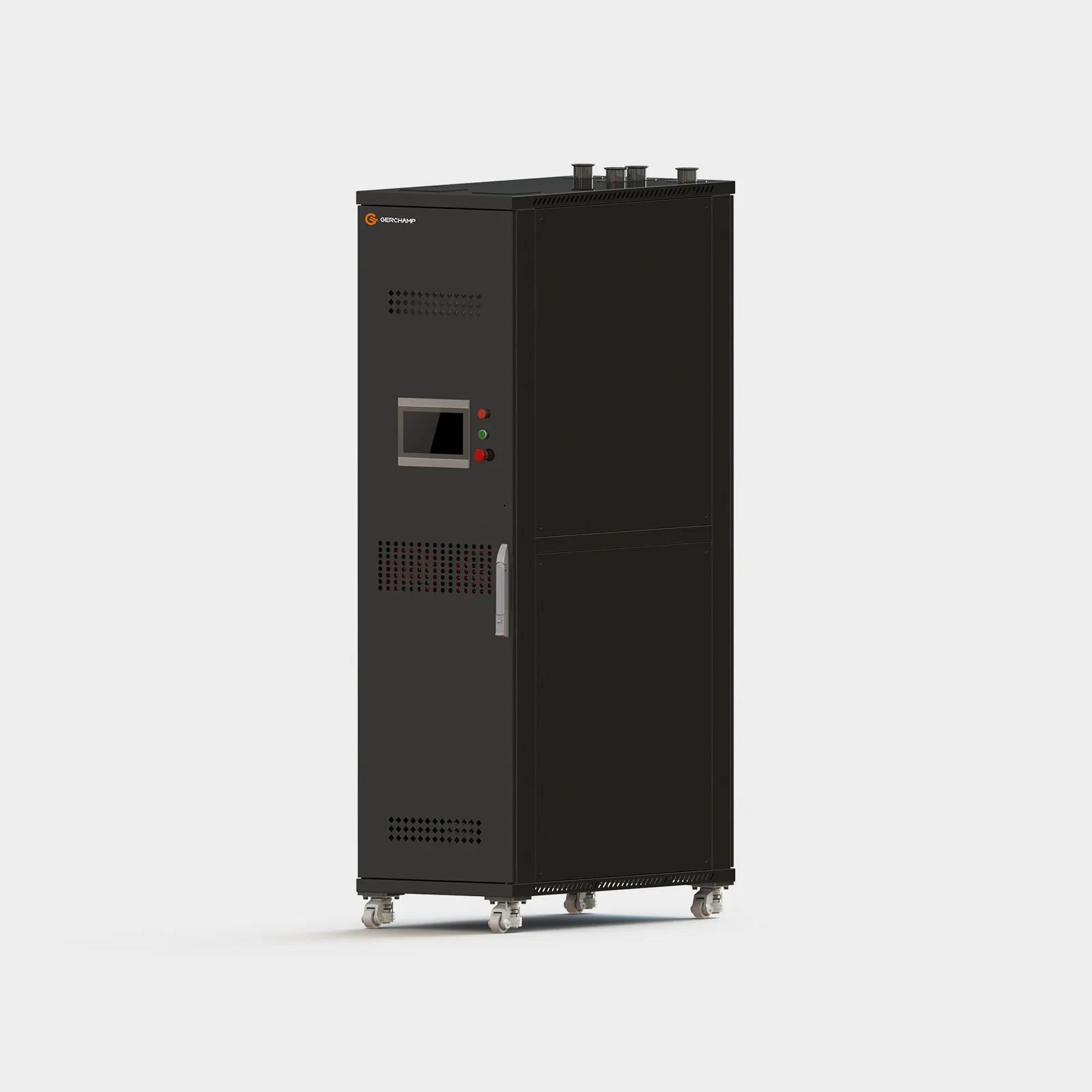
A sidecar unit stands beside the row it serves, close to the cabinets it cools. It keeps the rack space intact and shortens the hose run compared with a distant plant room. It takes floor area beside the row, and hose routing, service access and airflow clearance depend on the installation layout. How the three forms compare is set out in in-rack vs in-row CDU.
How the Modular CDU Layout Organizes the Parts
A modular CDU layout groups the parts into blocks that can be separated for service. The grouping follows service access, so the seams land where a technician needs them.
What a seam carries depends on the block. A pump block carries fluid, power, and signal. A heat rejection block carries fluid and, on an air-cooled unit, a fan supply. Whether a block can come out while the rest of the loop runs depends on its isolation, the redundancy available and the approved maintenance procedure.
Module seams and service access
A common split separates the pump and reservoir block from the heat rejection block. The filter and the control valves usually sit with the block they serve. Gerchamp’s CDU4175 L2A 175kW is built this way at 52U, with module weights listed separately on the datasheet for that model. How the blocks divide and how the weight splits decide what the site can do. Details are in modular CDU design.
Limits of modularity
A removable block is a service feature. It does not raise the capacity of one enclosure, and it does not create a second cooling unit. Adding capacity takes parallel units, which Gerchamp’s CDU4175 L2A 175kW product page lists as a supported arrangement, or a larger model.
Removability also has a limit set by the route. Whether a block can reach the hall depends on the door width, the lift, and the turning space on the way, and those belong in the project survey. For details, contact us.
The CDU System Boundary and What Sits Outside It
The CDU system boundary has three parts, and mixing them produces bad specifications. The first is physical: what the enclosure contains. The second is commercial: who supplies, installs, and warrants what. The third is technical: which outside conditions still drive the selection.
Keeping the three apart settles most arguments early. A part can sit outside the enclosure and still set a requirement inside it.
Enclosure contents
The enclosure contains the parts listed above, plus the internal pipework and wiring that connect them. Manifolds usually sit outside it, and internal manifold options exist on some products. Whether a given model includes them is a drawing question, answered per model.
Supply scope
Supply, installation, and warranty follow the contract documents. A project may buy cold plates, hoses, and manifolds with the IT equipment, with the CDU, or from a third supplier. The scope list settles it.
External design inputs
External equipment still sets design inputs. A chiller or a cooling tower sets the facility water temperature on a liquid-to-liquid unit, and the room air temperature sets the reference on a liquid-to-air unit. Cold plates and external pipework set the pressure drop the pump must overcome, whether or not they are in the CDU supply.
The specification then splits by side. On the facility side, a liquid-to-liquid unit needs the inlet temperature, the available differential pressure at the CDU ports, and the water quality limits. On the IT side, it needs the design flow, the differential pressure the pump delivers, the supply temperature and its tolerance, and the coolant quality limits. Design pressure and its test requirement apply to each liquid circuit. The conditions depend on the project. For details, contact us.
Frequently Asked Questions
Are all CDU components integrated into one enclosure? Not necessarily. Filters, expansion tanks, filling equipment or manifolds may sit inside the CDU or outside it, depending on the architecture and the product configuration.
Does every CDU have a plate heat exchanger? No. A plate heat exchanger appears in liquid-to-liquid units, where facility water takes the heat. A liquid-to-air unit rejects into room air through a coil and has no facility-water connection.
Is a larger enclosure always more capable? No. Capacity follows the rating conditions, which include the approach temperature, the coolant, the flow, and the ambient. A 4U unit and an in-row unit can sit in the same product line with very different ratings.
The Bottom Line
Reading a CDU datasheet comes down to four questions:
- which group changes with the architecture, and which parts serve it
- which functions are integrated and which are optional on this model
- where the enclosure stands, and what that costs in rack space, floor area, and clearance
- which outside conditions still set the duty, even when the equipment is not in the supply
Gerchamp’s CDU4175 L2A 175kW product page gives a full data set, with the port data and module weights for a 52U sidecar unit.