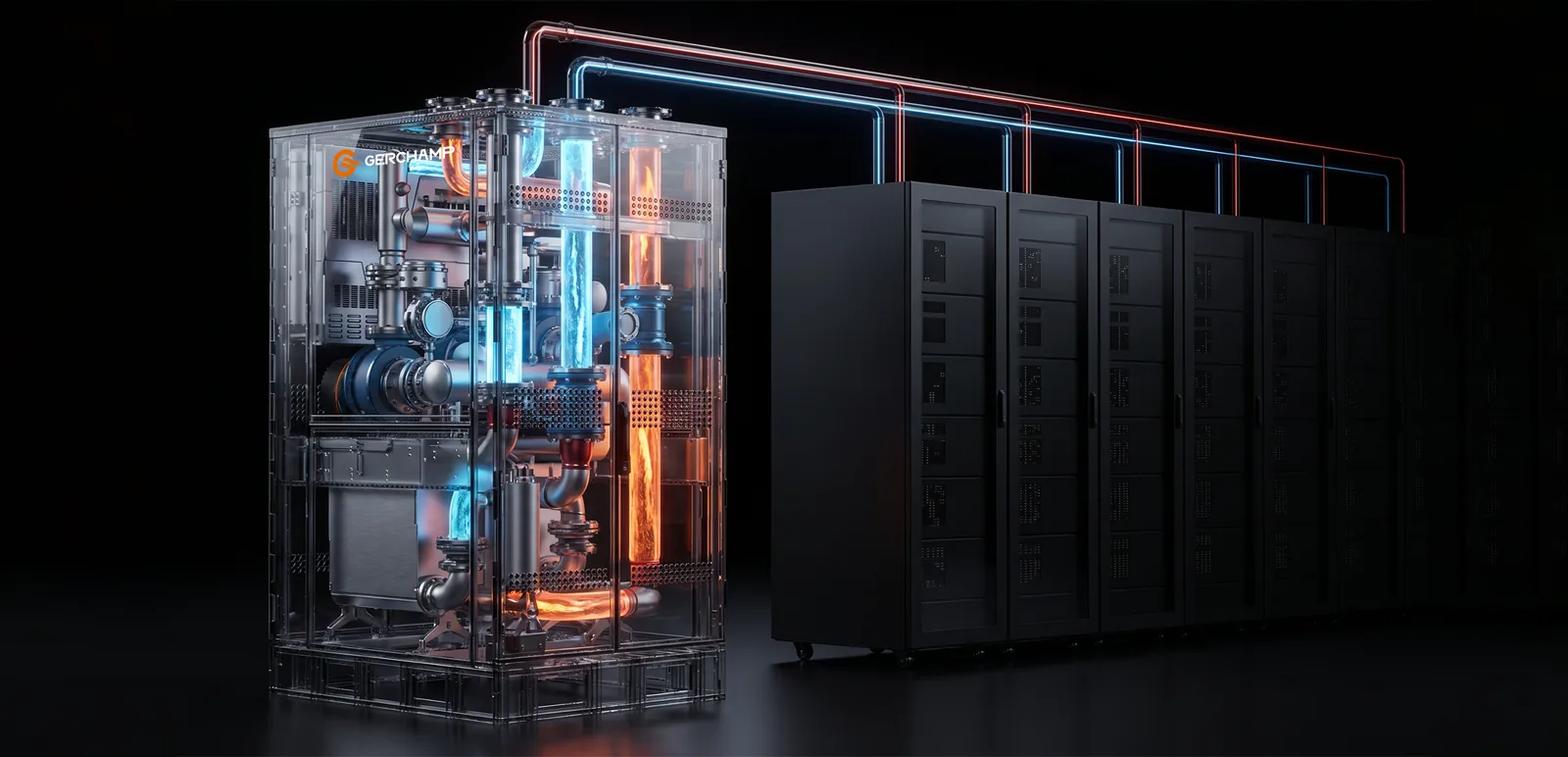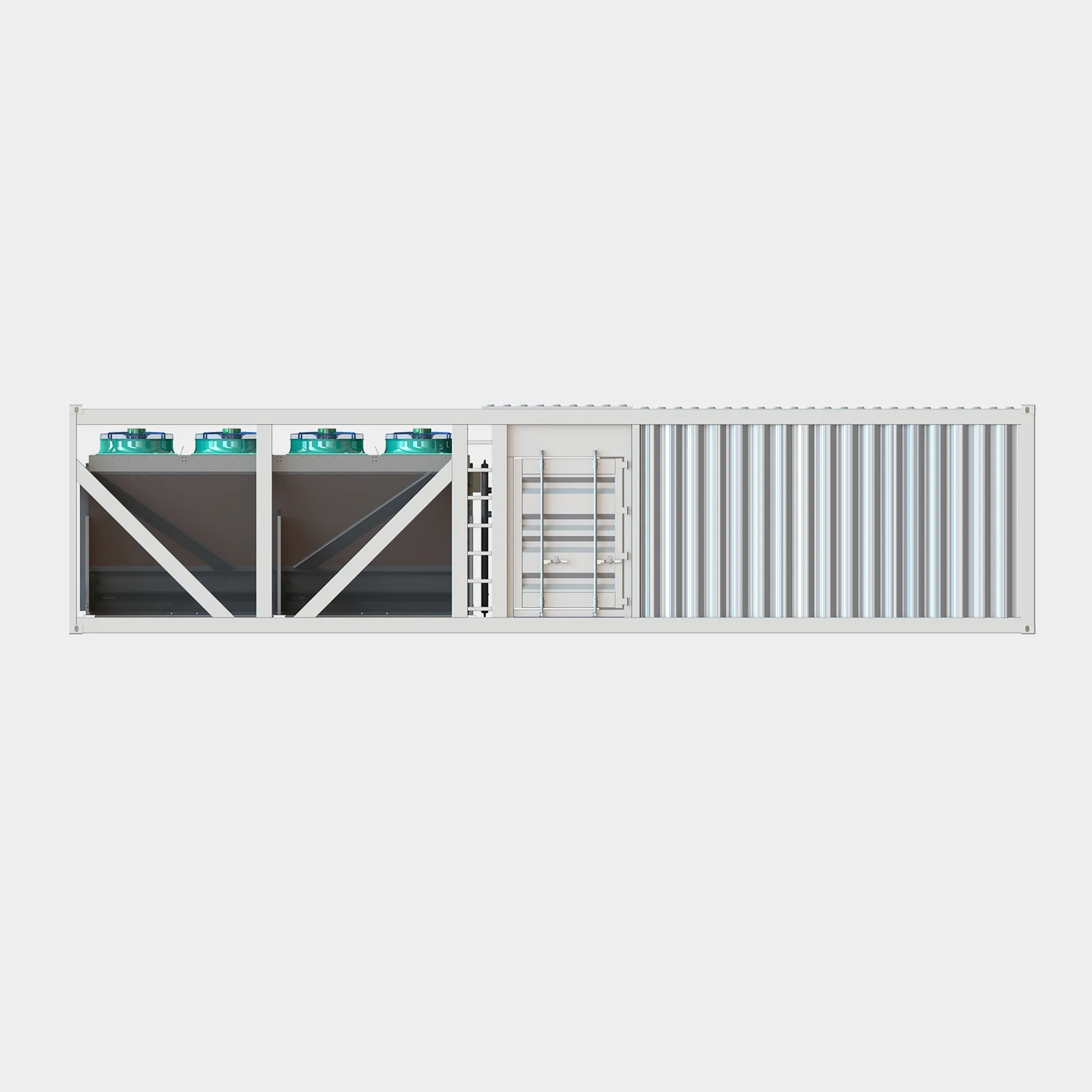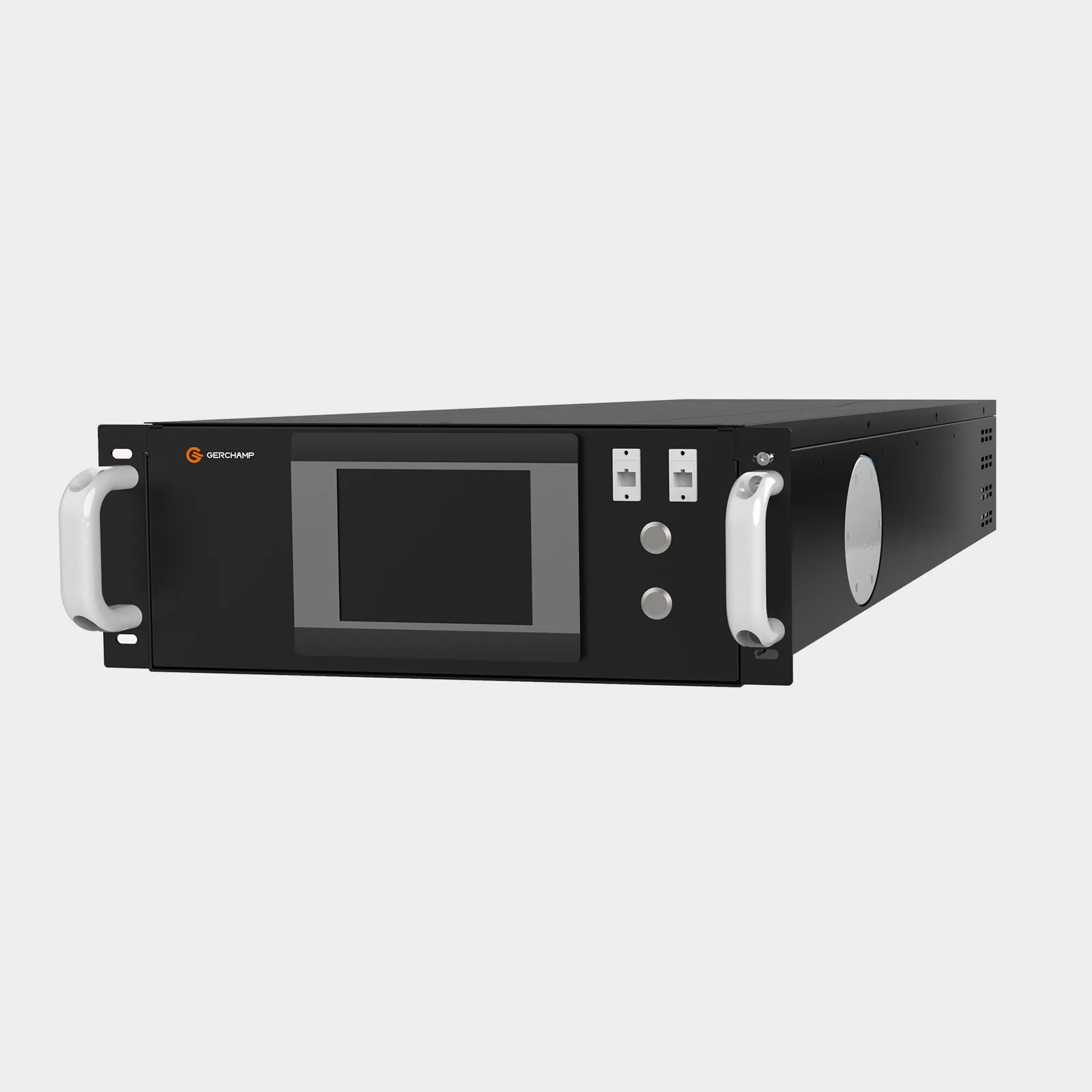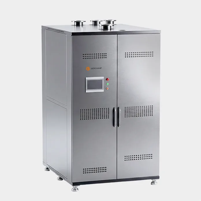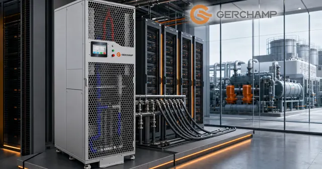
The CDU vs chiller question starts with a systems drawing, where both devices carry water and look alike. A conventional CDU transfers heat from the IT cooling loop to facility water or room air. A vapour-compression chiller uses a refrigeration cycle to produce chilled water at a specified temperature.
This page compares a conventional CDU with a vapour-compression chiller, the type most data halls run. A plant can also run free cooling, in full or for part of the year.
The CDU system boundary and what sits outside it section sets out how the unit and the plant divide the cooling work. A chiller is the typical source of facility water temperature.
Cooling Chain Position of Each Device
A data hall cooling chain runs from the chip to the outdoors. A CDU sits near the IT load and a chiller plant sits on the facility side, and position explains most of the behaviour that follows.
The Plant Side of the Chain
A plant produces water at a temperature the project needs. A vapour-compression chiller does that with a compressor, an expansion device, and two heat exchangers held at different pressures.
The condenser rejects the heat it collected. An air-cooled unit rejects it straight to outdoor air, and a water-cooled unit passes it to a cooling water loop and then to a cooling tower.
Free cooling changes the equipment and leaves the position as it is. A dry cooler or a cooling tower can serve the facility side whenever it holds the water cold enough for the CDU to meet its secondary supply target at the design load and flow.
The Loop That Reaches the Rack
A CDU sits between the facility water and the rack loop. Its secondary side reaches the manifold, the hoses, and the cold plates inside the servers.
Its job is to hold the conditions the racks receive and pass the collected heat to the medium on its other side, usually facility water and sometimes room air.
The Handover Point
The primary connections mark a typical split. The facility cooling system establishes the primary-side temperature and hydraulic conditions. The CDU regulates the secondary loop through the pumps, valves, sensors, and control modes it has available.
Flow and differential pressure belong to the same hydraulic circuit, so the control mode decides which one the unit holds. Control scope and contract responsibility are agreed per project, and neither has to follow the connection point.
The CDU Supply Temperature Limit
Inside a CDU enclosure sit pumps, an exchanger or a coil, valves, filters, sensors, and a controller. Heat crosses that equipment. The cooling medium temperature therefore limits the coolant supply temperature a CDU can achieve.
No Refrigeration Cycle Inside
A conventional CDU has an exchanger or a coil and a pump set. It carries no compressor, expansion device, or refrigerant circuit of its own.
Heat crosses the exchange surface from the warmer fluid to the cooler one. The direction is fixed, so the secondary loop cannot leave the CDU colder than the medium that absorbs its heat.
Supply Temperature Against the Sink
For a conventional CDU without refrigeration, the achievable secondary supply temperature is constrained by the cooling medium temperature and the approach at the exchanger. On a liquid-to-liquid unit the reference is the facility water inlet temperature. On a liquid-to-air unit it is the air entering the cooling coil.
The rack inlet temperature may differ from the CDU outlet temperature. Heat gain or loss along the path changes the fluid temperature, and sensor position changes how the two readings compare.
Narrowing the Approach
The gap is a property of the exchanger and the duty it carries. A larger heat-transfer surface, a different plate pattern, or higher flow on either side may narrow it at the same medium temperature. Those choices also change pressure drop and pumping power, and have to be checked against the required duty.
Two routes therefore exist for a colder rack loop. One lowers the cooling medium temperature, set by the plant on a liquid-to-liquid unit and by the room air on a liquid-to-air unit. The other narrows the approach, which depends on exchanger selection and the operating conditions at the project load.
The pump set delivers flow and differential pressure. Changing the flow changes the heat-transfer conditions in the exchanger, and it cannot move the loop below the cooling medium temperature.
CDU Control Scope and Setpoints
A plant holds the temperature of the water it produces, and a CDU holds the conditions the racks receive.
Temperature at the Rack Inlet
A CDU regulates secondary supply temperature with the means its design provides. Depending on the architecture, those may include a primary-side control valve, bypass mixing of return flow, or fan speed on a liquid-to-air unit.
Pump speed primarily regulates flow or differential pressure. It also changes the heat-transfer conditions, so it can contribute to temperature regulation depending on the control strategy and the range available. The methods and limits come from the model’s control description.
Flow and Pressure Modes
A CDU holds flow or differential pressure according to its control mode. A constant-flow unit holds flow, a constant-pressure unit holds a differential pressure setpoint, and some units switch between the two.
Which mode suits a project depends on how the rack loop is balanced and what the cold plates expect.
Plant Pump Control
A chiller plant regulates the temperature of the water it produces. The pumps that move that water around the site are a separate control problem, and they usually hold a differential pressure at a header far from the racks.
The CDU then regulates that supply to the conditions the cabinet needs. Measurement points are set in the design, and the two loops are commissioned as separate systems.
CDU Capacity Rating and Chiller Rating
Both ratings are heat power in kilowatts, so the numbers convert directly. What does not convert is the boundary each figure is measured across, or the conditions attached to it.
| CDU | Vapour-compression chiller | |
|---|---|---|
| Main function | Move heat, hold loop conditions | Produce chilled water through a refrigeration cycle |
| Temperature capability | At or above the cooling medium temperature | Below the heat-rejection medium within its rated operating range |
| Control target | Supply temperature, flow, differential pressure, by control mode | Produced water temperature |
| Rating conditions | Inlet temperatures on both sides, flows, fluid, approach | Evaporator and condenser temperatures, flow |
| Electrical input | Mainly pumps, fans and controls, depending on configuration | Mainly compressor and auxiliaries |
Rating Boundaries and Conditions
A chiller rating describes heat removed at the evaporator, quoted with an evaporator leaving temperature, a condenser entering temperature, and a flow. A different condenser condition gives a different figure from the same machine.
A CDU rating describes heat moved on the secondary side, quoted with conditions on both sides: coolant properties, the inlet temperatures, the flows, and the approach at the exchanger. A narrower approach or a warmer primary inlet gives a different figure from the same hardware.
Cooling Capacity Against Input Power
Chiller literature lists cooling capacity and input power as separate numbers, and the same separation applies to a CDU. Its heat figure is not its electrical draw.
Condenser heat rejection is a third quantity. It carries the heat absorbed at the evaporator plus the energy the compressor adds to the refrigeration cycle.
Adding a CDU’s kW to a chiller’s kW counts heat twice when the CDU sits downstream of the same loop.
Matching Against a Project Load
Both figures are sized against the same project cooling load, each under its own rating conditions. The IT side sets the heat that has to leave the racks, and the CDU delivers it at the temperatures and flows the cold plates need.
When a chiller serves the same cooling path as a CDU, its evaporator-side capacity has to cover the load assigned to that path, plus pump heat and other auxiliary gains. Where free cooling carries part of the load, the chiller’s share follows the operating strategy. Ignoring the other system’s conditions may leave either device short of the required cooling capacity.
Frequently Asked Questions
Can a CDU replace a chiller? A conventional liquid-to-liquid or liquid-to-air CDU provides no refrigeration, so it cannot deliver fluid colder than the medium it exchanges with. It moves rack heat into facility water or room air, and it can run without a chiller when that medium is cold enough.
Does a CDU always need a chiller? No. A CDU can work with a dry cooler, a cooling tower, or a free-cooling plant when that source keeps the water cold enough for the CDU to meet the rack requirement. A liquid-to-air CDU rejects to room air.
Why can two 100 kW figures not be swapped directly? Each holds only inside its own rating conditions. A CDU quoted at a wide approach carries less heat at a narrow one, and a chiller quoted at one condenser temperature carries less at a warmer one.
The Bottom Line
A chiller produces chilled water through a refrigeration cycle. A CDU moves rack heat into a cooling medium and holds the loop conditions the servers see. The practical differences sit in the temperature limit, the control target, and the conditions attached to each rating.
Both capacity figures are heat power and both convert to the same unit. Matching them takes a project load, the temperatures and flows at the interface, and the conditions each figure was quoted at.