

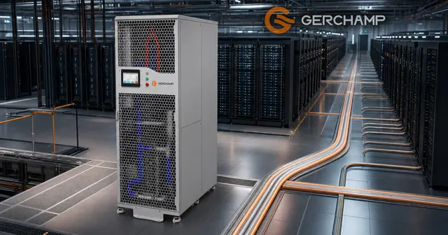
A megawatt CDU earns a place on the comparison sheet when a cooling zone carries a concentrated liquid load, has a distribution network that suits centralised cooling, and sits in a building that can take the unit. Whether it beats several smaller CDUs depends on usable capacity at site conditions, on the fault the project accepts, on the hydraulics to the worst-served branch, and on how the build is staged.
The parent article sets out the capacity range in the CDU capacity range across the Gerchamp line. This page compares the two arrangements on one basis.
Liquid Load Served by One CDU Group
Set the served zone before comparing unit sizes, because the load that zone puts into the liquid loop is the figure both arrangements meet.
Installed, Available and Post-Fault Capacity
Four figures need separating. Design liquid-cooling load is the heat the loop serving that group is expected to carry, and in a hybrid hall it differs from the total heat the racks release. Installed capacity is the sum of nameplate ratings. Available capacity is what those units deliver at the site’s temperatures, flows and coolant. Post-fault capacity is what stays deliverable after the agreed fault.
A redundancy target names the failure the system must tolerate and how much cooling has to survive it. Meeting that target may take more CDU capacity, an independent distribution path, or both, and the result is verified at the same site conditions.
Scope of the Served Load
The group may serve one row, part of a hall, or a zone that crosses rows. A load that fits inside one mid-size unit can still justify a larger unit, where the project wants fewer connections, headroom for growth, or a different maintenance model.
A megawatt rating describes device size, and deployment is a scheme decision.
Failure Scope Under a Given Topology
Unit capacity sets how much load one unit-level failure can expose, and the topology decides the actual failure scope.
Isolation and Load Transfer
Whether a failed unit takes its racks down depends on four conditions: whether the loop is dedicated or shared, whether the unit can be isolated, whether the remaining units can pick up the load, and whether power, controls or facility water are shared.
A shared header can stay a common failure point even when several CDUs are installed. A large unit sits inside a redundant arrangement when another adequately sized unit and an independently usable path exist. A bypass gives an isolation route, and on its own it carries no cooling.
The comparison needs one stated fault case for every option: which unit is out, for how long, at what load, and whether the event is a failure or planned maintenance. Each option then reports the duty still delivered at the served loads.
Component and System Redundancy
Redundancy has three levels, and each is verified on its own case. Component redundancy covers a pump or an exchanger. Unit redundancy covers a whole unit. System redundancy covers the loop and the plant.
Gerchamp’s CDU32700 L2L 2700kW carries two plate exchangers and a 2+1 pump set, two duty and one standby, as its product page states. That is component architecture. The duty available after one exchanger is isolated, and after a unit-level fault, follows the isolation and changeover design. The conditions depend on the project. For details, contact us.
Hydraulic Reach and Part-Load Operation
On the technology-cooling side the check is whether each arrangement delivers the design flow to the most demanding branch. The facility-water interface carries its own inlet conditions, and they are set out in facility water requirements.
Most Unfavorable Hydraulic Path
The most unfavorable branch is not always the furthest. Pipe size, flow, fittings, valve authority and cold plate resistance all enter, so distance is one input among several.
One unit feeding one header is one topology, and zone headers with several units are another. Required pump head follows the network and its losses. The comparison needs the header arrangement, the available external differential at design flow, the control range, and the margin left for later branches.
Header diameter affects the loss and the flow split, and the differential at each take-off also follows pump performance, total flow, valve settings and the resistance of the connected network.
Part-Load Comparison
Part load is an item to compare, and it takes the pump-staging sequence, the minimum stable flow, the pump and system curves, and the expected load profile.
An energy claim belongs on comparable operating points, and unit count alone supports none. Pump curves are read with the controls and the load profile beside them. The conditions depend on the project. For details, contact us.
Deployment Costs and Expansion Trade-offs
Deployment splits into the first build and every later addition, and the unit count moves both.
Initial Build and Expansion
The first build carries equipment, headers, connections and a commissioning scope. A later addition may carry pipe connections, control changes, testing and a planned interruption, and the scope depends on the interfaces reserved, on the isolation strategy, and on whether the new branch can be commissioned with the existing service live.
Consolidating capacity into fewer units may simplify some connections and monitoring points, and the count still follows the header, isolation and instrumentation design.
Site Constraints on a Large Unit
Gerchamp’s CDU32700 L2L 2700kW measures 1,200 × 1,200 mm and stands 2,400 mm high, with a published wet floor loading of 1,100 kg/m². Site planning also checks the point load at each support, the floor structure, access clearances and the transport route.
Height sets the clear height and constrains the replacement route, and transport dimensions, mass and the handling method come with the unit. Isolation valves are one condition for maintenance, and a bypass path with remaining capacity completes it.
Every row is read at the same design load, site conditions and fault case.
| Item | Fleet of mid-size units | One megawatt unit |
|---|---|---|
| Capacity at site conditions | Sum, corrected there | One unit, corrected there |
| Capacity after the agreed fault | Units left running | Lost unless a second unit is added |
| Common failure points | Header, power, controls, water | Its own control and connections |
| Part load | Sets running, staging | Pump staging and control range |
| Expansion | A repeated unit scope | Branch tie-ins to a header |
| Site | Spread across positions | One footprint, one route |
Frequently Asked Questions
Is one megawatt the threshold? No. A load reaching 1 MW does not require a megawatt unit, and a smaller load can still suit one.
Does a large unit save space? Not by itself. Footprint per kilowatt and the service envelope decide.
Is a dual-exchanger unit redundant? The published structure is two exchangers and a 2+1 pump set. The duty left after one side is isolated follows the isolating valves and the changeover design.
Can one 2,700 kW unit replace four 680 kW units? Not on nameplate alone. Four 680 kW units total 2,720 kW, and equivalence needs the same site conditions, redundancy case and transfer capability.
The Bottom Line
Neither arrangement wins by default. Both are tested on one liquid-cooling load, one set of site conditions, one fault case, one hydraulic duty and one staging plan.
A performance check against those five decides the scheme, and unit size changes the scale of the answers.