

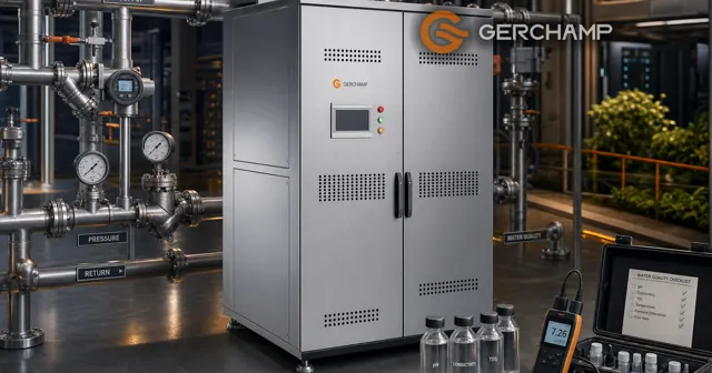
L2L CDU facility water requirements describe what the building delivers at the unit flange, and they hold as one set. Temperature alone does not settle a line, because flow, pressure and water quality decide whether that water can carry the load.
For the two-loop architecture, see What Is a Liquid-to-Liquid CDU. This page keeps to the facility-side conditions a project checks before selection and commissioning.
Facility Water Temperature and CDU Approach Temperature
Facility water temperature at the flange sets what the secondary loop can reach, since the CDU moves heat from the secondary loop into that water.
Facility Supply Temperature and Operating Range
The supply temperature at the flange is what the facility commits to. The secondary setpoint can only sit above the water arriving on the primary side.
The secondary supply leaves the unit above the facility supply, and the gap between them is the approach temperature difference (ATD). It pairs the CDU outlet on the secondary side with the CDU inlet on the primary side, and it depends on the exchanger and on the load.
Return Temperature and Heat Balance
A specified return temperature belongs with the heat load, the coolant and the flow it was set against. Supply and return can both be design targets, and both have to stay consistent with the heat balance.
A plant may also hold a return-temperature range for heat recovery or plant efficiency. Minimum-flow limits are hydraulic, and they are checked on that side.
Rated Approach and Operating Range
Gerchamp’s CDU3150 L2L 150kW, CDU3680 L2L 680kW and CDU32700 L2L 2700kW pages list rated capacities at an ATD of 4 °C. That is a rating condition, and secondary supply moves with load, flows and control state.
Keep three records apart: the rated design point, the operating range for the year, and the agreed abnormal conditions.
Facility Water Flow and Differential Pressure
Flow and differential pressure at the flange decide whether the unit receives the water its rating assumes, and the differential has to cover the exchanger, the valves, the strainer and the pipework on that side.
Design Flow and Its Load
Design flow follows the load and the temperature difference the facility loop permits, and the unit’s rating carries a flow of its own.
If the available flow falls below what a stated operating point needs, the unit may miss its target duty. Part-load behaviour follows the control and the flow condition at that time.
Pressure Values to Compare
Each pressure at the flange answers a different question, and a check pairs a facility figure with a limit:
- Equipment allowable pressure. What the unit and its internal piping may see, at a stated temperature and configuration.
- Facility operating pressure. Supply and return static pressure and their ranges, since one differential can sit at several absolute levels.
- Available differential at design flow. Measured where, at which flow, and in which operating state.
- Transient pressure. Events such as a pump start or a chiller changeover, each with its boundary named.
- Two-side relationship. The pressure condition the exchanger permits between primary and secondary.
Two comparisons sit behind that list. Containment asks whether every state, transients included, stays inside the allowable pressure of the unit and its parts. Hydraulic availability asks whether the differential at design flow covers the losses on that side and, where a control valve is fitted, its working range. Connection size, flange standard and isolation arrangement follow from those answers. How they land on a flange depends on the project. For details, contact us.
Control Valve Working Range
Where a pressure-independent valve is fitted, it holds its set flow while the upstream differential moves, inside its working differential and flow control ranges.
A valve regulates flow inside its range, and a shortfall in upstream differential is outside what it can correct.
Facility Water Quality at the Interface
Water quality at the interface describes what the chemistry does to the wetted path, and the limits are the ones every part in contact has to survive.
Limits at the Flange
ASHRAE’s reference table gives chloride below 50 parts per million on the facility side and below 5 parts per million on the IT side, with the facility figure described as guidance (ASHRAE, 2019, Table 1).
Those figures belong to two separate loops, and neither sets the other’s limits. Conductivity, pH and particle limits come from the wetted materials, the coolant and the treatment plan, so the specification carries a set that the table alone cannot supply.
A stricter value from a supplier or a treatment contractor still has to suit the materials and the other limits.
Sampling and Wetted Parts
On this page the limits apply to the facility-side wetted path: exchanger plates, valves, seals, strainers and piping. The secondary side carries its own specification.
Make-up water and circulating water answer different questions, since evaporation in an open loop concentrates dissolved solids. Sampling locations are defined per circuit, and one sample point does not cover both.
Facility Water Interface Schedule
An interface schedule consolidates the design values and the acceptance checks, and figures scattered across documents leave the interface unsettled.
Fields in an Interface Schedule
| Category | What the row records |
|---|---|
| Thermal | Design load, supply temperature with tolerance, return or ΔT constraint, secondary target |
| Flow | Design flow, control range, condition each applies at |
| Pressure | Operating pressure, available differential, allowable limit, transient, two-side condition |
| Medium and quality | Fluid, concentration, applicable limits, filtration |
| Mechanical | Connection size and standard, position, isolation, maintenance boundary |
| Responsibility | Provider, verifier, measuring point, acceptance record |
Tolerance and Abnormal Events
Tolerance describes normal operation, and an abnormal entry describes an event the plant can produce: a pump changeover, a chiller trip, a valve failure. Without a stated condition, a measured value is hard to compare with the design requirement.
Not every field takes a value and a tolerance: a connection takes a standard and a size, an abnormal entry a boundary condition, a verification method a test and a record.
Evidence at Each Stage
Three stages carry the evidence: design confirmation, the commissioning measurement, and the handover record.
The requirement becomes the commissioning basis first, and the result then verifies it. Whether a line can be verified that way depends on the records the project keeps. For details, contact us.
Frequently Asked Questions
Is one supply temperature enough on the schedule?
No. The rated design point and the operating range are separate records.
Can a pressure-independent valve raise the available differential?
No. It holds its set flow inside its working range and adds no differential.
Do both loops use the same chloride limit?
No. ASHRAE Table 1 gives 50 parts per million on the facility side and 5 on the IT side as guidance.
Who owns the interface schedule?
Ownership is assigned in the project specification or the responsibility matrix, with a provider, a verifier and an acceptance record named on each row.
The Bottom Line
Facility water sets the boundary the CDU works inside: temperature with its range, flow at its load, pressure against equipment limits, and quality across the wetted path.
The interface schedule is where a project turns those into checked lines, before selection.