

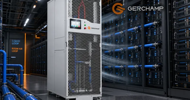
An L2A CDU architecture splits one job into two loops. One carries heat off the chips as liquid. The other hands that heat to the room as air.
That split decides what the equipment asks of the building, and where the cooling capacity tops out.
L2A CDU Architecture
An L2A CDU runs two loops, and they share neither a medium nor a pressure boundary. Naming them correctly settles which side of the equipment any given figure belongs to.
What L2A Means in a CDU Name
The letters describe where heat goes, not how the chips are cooled. In an L2A CDU the secondary side carries liquid and the primary side carries air.
A liquid-to-liquid unit differs in one respect. It rejects into a facility water loop instead of into room air, so it needs a water side behind it before it can operate.
L2A describes the rejection architecture of this equipment, not the building. A hall moving from air cooling to liquid cooling is doing separate work, and that work is an air-to-liquid retrofit.
The Primary Side Is Room Air
The primary side of an L2A CDU architecture is the air side. Room air crosses the coil, picks up heat, and returns to the hall.
The datasheet gives a primary airflow of 22,000 CFM. That figure is the unit’s demand on the room.
What the Two Loops Do Not Share
Nothing crosses between the loops except heat. The secondary loop is closed and runs at a design pressure below 2 bar, while the primary side is open to the hall.
| Secondary loop | Primary side | |
|---|---|---|
| Medium | PG25, 25 wt% propylene glycol | Room air |
| Boundary | Closed, inside the equipment | Open to the hall |
| Flow rate | <175 LPM | <22,000 CFM |
| Design pressure | <2 bar | Not applicable |
| Connection | 2-inch sanitary clamp | Air path |
That separation carries a practical consequence. Work on the air side never opens the liquid circuit, and work on the liquid circuit never disturbs the room.
A room-air rejection path suits halls that have air-handling capacity to spare and no chilled-water infrastructure at all.
It also suits phased deployments, where racks arrive over time and each one needs cooling as it lands rather than years ahead of arrival.
Gerchamp’s Bluearth CDU4175 L2A 175kW is one unit built on this pattern.
CDU Primary and Secondary Loop: Where Each One Ends
Each loop ends somewhere different, and that difference explains most of what follows. One ends at a coil. The other ends in the room.
The Secondary Loop Stays Inside the Equipment
The secondary side of the CDU primary and secondary loop pair leaves the cold plates warm and returns them cool. Its circuit sits inside the equipment and the rack it serves, so it never reaches the building.
The coolant is propylene glycol at 25 wt%, the mixture the datasheet specifies for this loop.
Liquid Cooling Secondary Loop Design: Flow and Pressure
Two figures fix the secondary side. A liquid cooling secondary loop in this unit runs below 175 LPM of flow and below 2 bar of design pressure.
The two are specified together because a loop has to deliver enough volume to every cold plate in the row while staying inside a pressure class its fittings can hold.
The connection is a 2-inch sanitary clamp, a fitting chosen for a circuit that gets opened during maintenance rather than drained.
Flow comes from pumps inside the unit rather than from the building, so the secondary side is self-contained by design.
That matters to a retrofit, because it means the liquid circuit arrives with the equipment instead of needing to be built into the hall first.
The coil is the meeting point. Warm fluid passes through it on one side, and room air crosses it on the other.
Heat leaves the liquid and enters the air, and the hall now owns it.
GPU rack heat rejection follows that same path in every L2A installation, whatever the rack happens to contain.
CDU Approach Temperature: The Gap That Fixes Capacity
Capacity is measured against a temperature gap, and in this architecture the room sets that gap.
What Approach Temperature Measures
CDU approach temperature is the difference between the coolant leaving the loop and the air entering the unit, which makes it a property of two streams rather than of the machine alone.
The datasheet lists two ratings for a single unit. It gives 175 kW at an approach of 10 °C and 125 kW at an approach of 5 °C.
Why the Air Side Sets the Ceiling
In a liquid-to-liquid unit the limit arrives from the facility water temperature. In an L2A unit it arrives from the room instead.
The air entering the unit carries whatever temperature the hall is kept at, so identical equipment behaves differently in two buildings.
The datasheet specifies a 35 °C ambient and a secondary loop at 45 °C supply and up to 60 °C return.
A warmer hall narrows the gap, and the two published ratings show what that costs. A capacity claim that omits the approach says little about a deployment.
| Rated condition | Published value |
|---|---|
| Capacity at an approach of 10 °C | 175 kW |
| Capacity at an approach of 5 °C | 125 kW |
| Ambient | 35 °C |
| Secondary loop | 45 °C supply, up to 60 °C return |
A hall that holds a wide gap reaches the higher figure. A hall that forces a colder coolant supply lands at the lower one.
Data Center Liquid Cooling Retrofit: What the Air Side Decides
A data center liquid cooling retrofit is usually described as a water project. Where the CDU rejects to room air, it is an air project instead.
What a Retrofit Actually Changes
The rack row gains cold plates and a secondary loop. The hall gains a distribution unit beside the row.
What it does not gain is a chilled-water system, a cooling tower, or floor penetrations for primary pipework. Those are the items a water-cooled path needs in place before the first rack can run.
Halls That Qualify
A hall qualifies when its air handling still has headroom at design conditions. That reserve is what a room-air path spends, and it is spent gradually as racks are added to the row.
Where the headroom is gone the approach is unavailable, and the alternative is a loop with a facility water side.
What a Room-Air Path Costs the Operator
The room’s air handling joins the cooling chain, whether or not anyone sized it for that role.
Every stage of the path has an owner. The white space, the hall’s air treatment, and the rack row each carry part of the load, and GPU rack heat rejection is only as strong as the weakest of them.
Gerchamp’s Bluearth CDU4175 L2A 175kW is an L2A CDU built to the two-loop pattern described above. The datasheet lists a 22,000 CFM primary side and a 175 LPM secondary loop at a design pressure below 2 bar for the CDU4175 L2A 175kW, with propylene glycol at 25 wt% as the secondary coolant.
Capacity scales by addition rather than by replacement. At its 175 kW rating, one CDU4175 L2A 175kW carries a fully loaded NVIDIA GB300 NVL72 without a chilled-water connection, and two units in parallel cover NVIDIA Vera Rubin NVL72.
FAQ: L2A CDU Architecture and Capacity Ratings
What does L2A mean in a CDU?
L2A stands for liquid-to-air. The secondary side carries liquid and the primary side carries air, so the unit rejects heat into the room rather than into a facility water loop.
Does an L2A CDU need a chilled-water connection?
No. The primary side is room air, which is what lets an L2A CDU architecture fit a hall that has no water side at all.
Why does the same unit carry two capacity figures?
Capacity depends on the approach temperature between the coolant and the room air. The datasheet gives a higher figure at a 10 K approach than at 5 K, so a capacity number is comparable only when the approach is stated with it.