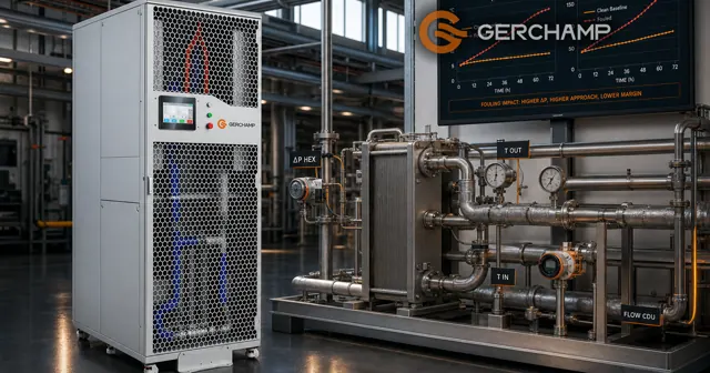
CDU heat exchanger fouling is a deposit on the wetted surface, and it acts on a unit in two ways: it adds resistance to heat flow, and it takes free area from the channel. The two effects can reduce heat transfer and raise flow resistance at different rates, so a site may meet one before the other.
The parent article places the exchanger in its section on pressure drop and fouling. This page covers the deposits, both effects, what each measurement can show, and how a cleaning route is chosen.
Plate Fouling and Where Deposits Form
Plate fouling starts with what the water carries, and three deposits behave differently.
Scale-Forming Salts
Some scale-forming salts, calcium carbonate among them under the right conditions, become less soluble as the water warms. Deposition also depends on ion concentration, pH and saturation, so warming alone does not decide it.
In a liquid-to-liquid CDU the primary side receives the heat, so its water runs warmer and the local wall temperature climbs with it. Whether scale forms follows that wall temperature and the chemistry, and the circuit label does not settle it. During normal cooling, heat flows from the secondary fluid into the primary circuit.
Established mineral scale is generally not removed by normal flow adjustments alone.
Suspended Solids and Corrosion Products
Suspended debris collects at channel entrances and in low-flow regions, and where it settles follows the geometry and the operating conditions. With an intact barrier between the circuits, corrosion products stay in the loop where they formed.
A strainer upstream holds the larger fraction, and the plate sees the rest.
Biofilm Growth Conditions
Biofilm forms on wetted surfaces where temperature, nutrients and stagnation allow growth. Make-up water and air contact at a reservoir can carry organisms in, and established biofilm resists treatment more than free-floating organisms do.
| Deposit | Where it forms | Signal it gives |
|---|---|---|
| Scale | Warm surface above saturation | Wider approach at the same duty |
| Suspended solids | Channel inlets, low-flow regions | Rising filter or section drop |
| Biofilm | Wetted surface with nutrients | Falling duty, rising drop |
Heat Transfer Degradation and Pressure Drop
A deposit moves the thermal margin and the hydraulic margin, and the two do not move at the same rate.
Thermal Effect at the Plate
A deposit adds resistance in series with the plate, so at comparable flows the coefficient falls. The duty then needs a wider temperature difference, or it falls at the same difference.
Where the control design permits, the controller compensates through flow, valve position or pump speed, and that spends control headroom. Once the margin is gone, the unit misses its target supply temperature or its duty.
Design work often carries a fouling allowance, sometimes written as a fouling factor. It represents an expected resistance for sizing, and it says nothing about the deposit actually present.
Hydraulic Effect in the Channel
At comparable flow and fluid properties, blockage or added roughness raises the pressure drop across the affected section. How the system answers depends on its control: a fixed-speed pump loses flow, a constant-differential arrangement drives the valve open, a variable-speed set may run faster and draw more power.
Order of Visible Signals
A thin film can widen the temperature difference while the pressure drop barely moves. Local blockage can show in flow split and pressure before the duty shifts. A control loop with margin can hold the supply temperature while its command changes.
Either symptom can appear first, and the order follows the deposit, margin and control design.
Fouling Diagnosis and Measurement Boundaries
Fouling diagnosis starts with what each measurement covers, since three pressure figures are easy to mix.
Measurement Boundaries
One figure is the exchanger’s own drop on one side. Another is the drop across the CDU connections, including valves, strainers and internal piping. A third is the filter differential, where a gauge exists.
Only the first describes the plate pack. A rise in the second can come from any component in that boundary, so these readings need a stated tap location and operating condition.
Signal, Cause and Check
| Observation | What it suggests | Still to check |
|---|---|---|
| Supply drifting above target | Less margin, a changed load, or a control action | Primary inlet, flows, valve and pump state, sensors |
| One side’s drop up at comparable flow | Resistance in that section | Tap location, fluid temperature, valve, baseline |
| Both sides changed | A shared condition first, then two separate faults | Operating point, instruments, then each side |
| Flow down at a fixed command | The operating point moved | Supply pressure, pump, valves, filters |
Control Response and Baseline
Where the control design permits, the system compensates through valve position or pump speed, so the first visible sign can be a changed command. Command and flow trends belong beside the temperatures.
A clean-condition baseline makes the comparison direct. Where a comparable clean curve or a validated model exists, it supports the assessment, and a single nameplate rating is not enough to confirm fouling.
Two readings at different flows describe different operating points, so the flow record sits beside the temperature. What a site can measure depends on its taps and records. For details, contact us.
CDU Heat Exchanger Cleaning Decisions
A fall in thermal performance or a rise in pressure drop starts with a check of the operating point and the boundary, and not with a cleaning order. Where fouling is a credible cause, the method follows the deposit, the pack construction and the procedure approved for that unit.
Cleaning Justification
Three things come before a method: a comparable operating point, a known measurement boundary, and other causes excluded, including primary inlet temperature, strainer loading, valve and pump state. Where fouling stays the likely cause, the deposit and the pack construction point to the route.
Method by Deposit and Structure
Approved flushing or backflushing may remove loose debris, depending on the design and blockage. A chemical clean is chosen for the identified deposit and the permitted materials, using the procedure approved for that unit, because the fluid reaches seals and brazing as well as plates. A sealed pack rules out opening the plate stack, and the weight then falls on treatment, filtration and cleaning in place.
Verification After Cleaning
Duty at the commissioning condition is one result, read at comparable flows and temperatures. Integrity, leak tightness and the refill conditions are others, and a performance figure does not stand in for them. Where the pack opens, it is also the moment to inspect gaskets and plate edges. Which records prove recovery depends on the project. For details, contact us.
Frequently Asked Questions
Does fouling always raise both the temperature difference and the pressure drop? No. A thin film can move the thermal figure alone, and a control loop can hide it meanwhile.
Can pressure drop show which side fouled? It covers the section it measures. A side’s own drop takes readings upstream and downstream at comparable flow.
If the supply temperature still holds, is the unit clean? Not necessarily. The control may be spending headroom through valve position or pump speed.
Can a strainer replace water treatment? No. A particulate strainer holds suspended solids, and dissolved scale-forming ions pass through.
The Bottom Line
A deposit acts on two things at once: resistance to heat flow, and the free area of the channel. They arrive at different rates, so one reading rarely settles the question.
A maintenance decision rests on three things: the boundary behind a pressure reading, the control state behind a temperature reading, and the deposit plus the pack construction behind the cleaning route.